|
Ibex Battery Systems
Operation Manual |
|
|
S12BD-5.0/24DC Operation Manual |
Recommended Battery 10Ah or larger lead-acid batteries known as SLA (Sealed Lead Acid), VRLA (Valve Regulated Lead Acid), or AGM (Absorbed Glass Mat) - all are equivalent.
Gell cell and flooded automotive batteries are not compatible with this charger.
Many 10Ah batteries should not be bulk or absorption charged (14.7V) at more than 2.5A.
There's no maximum battery current spec at the float voltage (13.8V).
For this reason, when the charger's output voltage rises above 13.8V, the current limit is throttled back to 2.5A.
If the combined application load plus battery charging current exceeds 2.5A, the charger's output remains at 13.8V where the current limit is the full 5.0A.
Combination Charger/Power Supply The unit is designed to be permanently connected to the battery and the application load. When AC mains or optional DC power is available, the unit charges and maintains the battery while also powering the application load. When the input power fails, the battery continues to power the load with no service interruption. The current draw by the load does not interfere with the operation of the charger. Mounting The output voltage of the charger is temperature compensated to match the requirements of a sealed lead-acid battery. The charger and battery should be mounted in the same enclosure so they experience the same ambient temperature. Ambient temperature differences between the charger and battery have little effect during battery charging (bulk mode or absorption mode). If, however, the temperature difference is greater than 10C during float charging, the charger's output voltage may no longer be correct for long-term battery charge maintenance. The charger is designed to be mounted inside a chassis or equipment rack. There are four press-in standoffs in the bottom of the chassis. These have a minimum of 0.187 inch of available 6-32 threads to be used for mounting. Also, there are eleven 0.201 mounting holes in the side and the bottom of the chassis suitable for #10 hardware. Because the power transformer is the unit's heaviest component, using #10 machine screws through the four mounting holes on either side of the transformer is the most secure option. If the unit is not to be subjected to large shocks or vibrations, then the other mounting holes may be used instead.When using a small, non-metallic enclosure, a small fan may be necessary to keep the enclosure temperature within the 60C maximum for full current output. The ambient may rise as high as 85C without damage to the charger, but the maximum output current is automatically throttled back above 60C. Also, high temperatures drastically shorten battery life. If high operating temperatures are unavoidable, consider using a battery specified for +80C operation. Enersys is one possibility. With a large enclosure and adequate ventilation, a fan should not be needed. Input Power The charger is designed to be powered from the 120/240VAC 50/60Hz mains or from a 17-32VDC source. Both an AC and DC source may be energized at the same time with no ill effects. The rectified/filtered AC voltage is diode-or'ed with the DC input. Whichever voltage is higher runs the unit. The line input should be externally fused at 2.0A(120VAC) or 1.0A(240VAC). The four power transformer line terminals must be connected as follows (two primaries, 1-2 and 4-5). It is important that both primary windings be used. Do not use the charger with just one winding connected. |

|
|
| If the DC source is a solar panel, the panel should not be rated higher than 12V or 18V. Do not use a 24V panel (its open circuit voltage is usually over 32V). Observe the absolute 32VDC limit. When powering from a panel, the unit automatically runs in MPPT mode (maximum power point tracking) when appropriate. If a solar panel is used, a 100 watt unit (or larger) is recommended. For winter or constant cloudy conditions, consider using two panels mounted at a shallow inverted "V" angle to catch both morning and afternoon light. When using mulitple panels, they must be connected in parallel. Series connection must not be used because the resultant voltage will exceed the 32VDC limit. | |

|
|
| Output Terminals | |
|
"PWR" (Power Signal) has two programmable behaviors as detailed below. The signal can either indicate the presence of input power or battery charging/discharging status. "CHG" (Charging Signal) has two programmable behaviors as detailed below. The signal can indicate a combination of charging status or battery voltage. The "PWR" and "CHG" signals are supplied by digital 5V sources via 300 ohm equivalent resistance and may power standard non-resistor LEDs or CMOS logic. "-" (Negative Returns). The five terminals labeled "-" are common to the PCB ground and can be used interchangeably as ground returns. "+FN" (Positive Fan Source) The unit can run a small 12V fan for cooling the inside of an enclosure. A 12V/0.25A fan is recommended. The fan is switched on when the ambient temperature rises above 45C and off at 40C. Whatever current the fan consumes is drawn from the 5.0A total available current. The fan is run at a reduced voltage to allow it to operate at +85C (exceeding its normal +60C rating). "-FN" (Negative Fan Return) This is the return for the "+FN" source, not one of the "-" terminals. "+DC" (Positive DC input power) An optional 17V-32V DC input instead of (or in addition to) the 120/240VAC input. "+BA" (Positive Battery Connection). "+LD" (Positive Application Load Connection). Normal LED Signal Behavior (18K programming resistor removed) PWR Signal Reports the status of the unit's input power. On if the input power is sufficient to operate the unit, off otherwise. Low Input Power (Brownout) Conditions Because the unit may be powered from a solar panel, there are often dim-light conditions which results in insufficient input power and compromised unit operation. If the "PWR" signal is on, there is enough input power to operate the unit. The unit supplies current to the battery and load but it may not be as much as required. Under this condition, the "CHG" signal flashes as described below, indicating that the battery is not being charged but that the unit is supplying some level of current - which helps slow the rate of battery discharge. As the solar panel starts to receive stronger light and generate more output, the "CHG" signal becomes steady indicating that the battery is experiencing a full charge cycle. CHG Signal This signal reports the status of the battery's charge/discharge state. If "PWR" is on and "CHG" is on, the charger is in the bulk or absorbtion mode of a normal charging cycle. "CHG" goes off when the battery is fully charged and the charger has switched to float mode. This is the normal action to expect when the unit is powered from the AC mains or from a properly sized solar panel in full sunlight. If "PWR" is off, or is on but with insufficient unit input power, the battery in not being charged and is slowly discharging as it supplies current to the application load. In this condition, the "CHG" signal flashes the battery voltage code as shown in the diagram below. Power Failure Operation When the charger's line voltage drops to a level too low for proper battery charging, the charger switches to power-fail mode. The charger does not disconnect the "+BA" from the "+LD" terminal unless the charger is in power-fail mode and the battery voltage drops to the disconnect level.In power-fail mode, the charger maintains a connection between the "+LD" terminal and the "+BA" terminal. The charger also constantly monitors the battery voltage. During this time, the charger can use the "CHG" terminal to report the level of the battery voltage by providing a series of on-off pulses.
|
|

|
|
|
The first 2000 millisecond pulse signals the start of the pulse train. This is followed by a 500mS off time. There follows a series of from zero to five 66mS pulses, with a 250mS spacing, followed by a second 500mS off time. The pulse train repeats this pattern continuously. The pulse-width tolerance is +- 5%. The number of 66mS pulses is determined by the battery voltage.
5 pulses: Voltage = 12.50V and above (80% - 100% battery charge left). If the battery voltage drops to 10.80V, a 30 minute timer is started. Should the battery voltage rise above 10.80V during this time, the timer is reset. The voltage must remain below 10.80V continuously for 30 minutes for the battery to be disconnected from the "+LD" terminal. If the battery voltage drops to 10V, the battery is disconnected immediately. The unit switches off and both LED signals are off. When line power is restored, the charger reconnects the "+LD" terminal to the "+BA" terminal and restarts a battery charging cycle. When powered from an AC source, a severe brownout causes the same behavior. Alternate LED Signal Behavior (18K programming resistor installed) A programming resistor (18K, 1/4W, 5%) is connected between the "CHG" terminal and one of the "-" terminals (see the photo above). An LED on the terminal does not interfere with the resistor. This reporting mode may be more useful for remote applications. PWR Signal: Does not report the status of the unit's input power. On if the battery is being charged or is fully charged and being maintained.Flashing - (1Sec On, 1Sec Off) if the battery is being discharged. CHG Signal: Reports adequate battery voltage. On if the battery voltage is at or above 11.75V Off if the battery voltage is below 11.75V (less than 20% charge left) Charging Cycle When AC (or DC) power is turned on, the charger begins a charging cycle. This occurs even if the battery is fully charged. A fully charged battery draws a miniscule charging current and is not damaged by the charging cycle. The charger never forces current into the battery. It sets an appropriate output voltage and allows the battery to draw whatever current needed for proper recharging. This charging cycle lasts for at least 2 hours. A charging cycle is also initiated if the charger goes into current limit. This may be because the load has drawn more than the maximum current capability of the charger. Also, a charging cycle is initiated after every 26 days of uninterrupted power, to equalize the charge in each of the battery's cells. Over time, the charge level in each of the six battery's cells can become unbalanced. Whenever the current draw of the load exceeds the current limit of the charger, the battery must make up the difference. This partially (or completely) drains the battery requiring that a charging cycle be performed when the excess current draw is removed.Enhanced 3-Mode Charging This unit automatically charges the battery in three modes (bulk, absorption, and float charging). Because the charger is controlled by a microprocessor, it has the "intelligence" to determine whether or not a load is connected across the battery as it is being charged and to compute the ideal charging time for each charging mode. Because of this, the charger can be used to charge stand-alone batteries or as a combination charger/power supply. In either application, the charger properly charges the battery, using each of the three charging modes, with no danger of the charger locking itself into the absorption mode (see "Why some chargers fry batteries").Mode 1 - Bulk Mode: The charger is in current-limit and delivers its maximum rated current to the battery. It is in this mode that the battery receives most of its recharge. If the application load is connected during the charging cycle, the load draws whatever current it needs and the battery is recharged with the rest. When the battery voltage rises to approximately 14.7V, the battery is at a 75% to 90% recharged level and the charger switches to absorption mode.Mode 2 - Absorption Mode: The charger is in a constant-voltage mode delivering approximately 14.7V to the battery. It is in this mode that the battery is brought to a 100% recharged level. The charger's microprocessor calculates how long to keep the charger at the elevated absorption mode voltage. It doesn't matter if a load is across the battery during charging. The charger compensates for any current stolen by the load and completely recharges the battery. Mode 3 - Float Mode: The charger is in constant-voltage mode at a lower voltage than in absorption mode (approx. 13.8V). This allows the battery to draw just enough current to make up for its internal leakage current. When the charger is in this mode, the battery may remain connected to the charger for all of the battery's service life with no damage to the battery. If the battery is removed while being charged, the charger attempts to continue charging the (now-disconnected) battery. It automatically resets itself to the float voltage after an hour or two. If the battery (or a different battery) is connected to the charger during this time, the charger figures things out and re-calibrates its charging times to properly charge whatever battery is connected to it. The exact voltages required to recharge the battery during all 3 modes automatically vary with ambient temperature. |
|
|
Battery Connection Connect the positive battery terminal to the charger's "+BA" terminal.
Connect the negative battery terminal to one of the charger's "-" terminals.
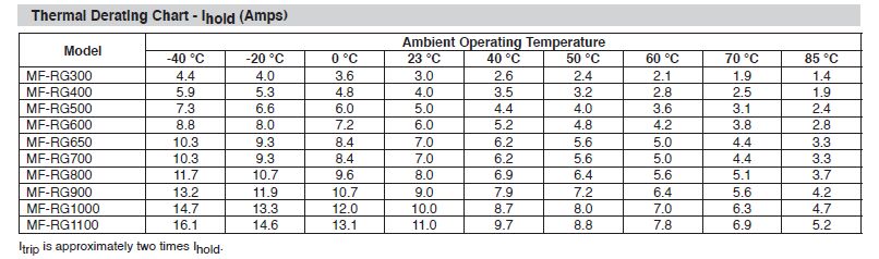
The five "-" terminals are all common on the PCB and are the interchangeable returns for everything: the battery, LEDs, and the application load. It's recommended that all battery and load connections be made with 16AWG wire or heavier. When off, the charger draws very little leakage current from the battery (<20mA) and so may be permanently connected. The load does not have to be disconnected when charging the battery. Do not over tighten the terminal screws. The output terminal block is plastic. The proper torque is 50 inch-ounces (0.4Nm). The battery should be fused close to one of its terminals. polymeric fuses work well. Size the fuse according to the current draw of the application. Not fusing the battery is a mistake. A battery can deliver a truly large current into a short circuit which can melt wires or start a fire.LED Connections Connect the anodes (+) of the user-supplied indicator LEDs to the "CHG" and "PWR" terminals. Connect the LED cathodes to a "-" terminal. Use LEDs or LED assemblies that do not have series resistors unless it is desired to reduce the LED current further (approx. 10mA). Load Connection Connect the optional load to the "+LD" terminal. The "+LD" terminal is normally connected internally by the charger to the "+BA" terminal via a power MOSFET switch. The application's load returns to a "-" terminal. In the event of a line power failure, the charger maintains the connection of the two terminals while constantly monitoring the battery voltage. If the battery voltage drops to a level that may damage the battery, the charger disconnects the "+LD" terminal from the "+BA" terminal. When line power is restored, the charger reconnects the "+LD" terminal to the "+BA" terminal. It is permissible to connect the load directly across the battery if the charger's battery-disconnect feature is not desired. It is also permissible to use the unit as a stand-alone battery charger with no load connected. Load Current The load may draw up to 7A (RMS) at room temperature. The charger supplies up-to its maximum output current with the battery supplying the rest. The "+DC" and "+BA" terminals are fused on-board with polymeric fuses (Bourns RG650 or equiv) which dictates maximum RMS current at higher temperatures. Caution: Although the charger portion of the unit is current limited at 5.0A and is thus short-circuit proof, there is no current limit for the battery. A short circuit at the "+LD" (Load) terminal causes a huge battery current surge which damages the battery-cutoff circuit. Although there are polymeric fuses at the "+BA" terminal (and hopefully at the battery), their responses are too slow to protect the MOSFET battery switches. Before connecting the battery, check the application's resistance to ground at the "+LD" terminal.
|
|